Basic Overview of Interface
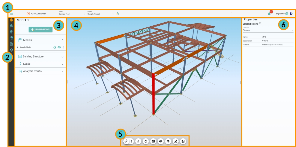
After you login to ALLPLAN AutoConverter you will see the application interface (Figure 1), which consists of the following components:
(1) Top bar
(2) Workflow selection bar
(3) Workflow specific panel
(4) 3D scene
(5) View settings
(6) Property panel
(1) Top Bar

Top bar content always stays the same no matter which workflow is selected (Figure 2). The top bar consists of the following components:
(a) Hamburger menu (with additional options when expanded)
(b) Team selection
(c) Project selection
(d) Project creation
(e) Notification bell
(f) Language selection
(g) Log out button
(a) Hamburger menu
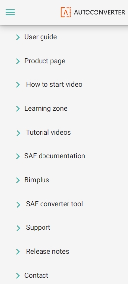
When the hamburger drop down menu is expanded, there are multiple options to use (Figure 3).
-
User Guide: Navigates you to the ALLPLAN AutoConverter user guide.
-
Product page: Link to the Bimplus website.
-
How to start video: Embedded video about quick start with ALLPLAN AutoConverter.
-
Learning zone: Link to the Bimplus learning zone.
-
Tutorial videos: When expanded, there are numerous embedded tutorial videos with specific features in ALLPLAN AutoConverter (all videos can also be found on the SCIA Engineer YouTube channel).
-
SAF documentation: Since ALLPLAN AutoConverter supports exporting to SAF format, this link leads to official SAF format documentation.
-
Bimplus: Link to the Bimplus portal.
-
SAF converter tool: Link to the SAF converter support website (tool for converting SAF files to Dlubal RFEM 5 excel input and to native Autodesk Robot files). When expanded, offers the option to report an issue, link to FAQ, and contact information for SCIA Engineer.
-
Support: Report an issue to Technical Support at Allplan and visit the FAQ.
Release notes: Provides up-to-date overview of released improvements (UserStory) and fixes (Bug).
-
Contact: Fill out the form to contact Technical Support and other entities at Allplan.
(b) Team selection
Select the Bimplus team you want to work in.
(c) Project selection
Select the specific project you want to work in.
(d) Project creation
Create a brand-new project, which is also automatically created on Bimplus.
(e) Notification bell
When the notification bell is in an active state (colored circle with number inside, Figure 4), it means you have unread messages. Click on the notification bell to show the new messages. Messages can be marked as read by clicking the orange check-mark button on the bottom right of the message. In case you have more unread messages, the latest message is at the bottom.
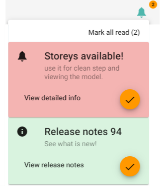
The notification bell has two types of messages:
New release of ALLPLAN AutoConverter: A notification with release notes will be shown with every new release. Click "View release note" to see the complete release notes.
General message: A general message usually informs you about newly available functionality. Click "View detailed info" for more information about the new functionality and possibly a tutorial video.
(f) Language selection
The following languages are supported by ALLPLAN AutoConverter: English GB, Czech, German, French, Portuguese
(g) Log out button
Click this button to log out of your ALLPLAN AutoConverter account.
(2) Workflow selection bar
The workflow selection bar offers available workflows based on your license. All available workflows are shown on Figure 5.

-
 Manage Models: The model manager allows you to upload new models, control which models are viewable in the 3D scene, and inspect the models in the 3D scene.
 -
 Convert Structural model to Analysis model: Shortly "S2A" is a process that guides you from the structural model at the beginning of the workflow to the analysis model at the end of the workflow.
 -
 Update existing Analysis model from Structural model: An update workflow that guides you through the process of updating the analysis model with selected changes from a revised structural model.
 -
 Compare revisions of Analysis model: An update workflow that compares changes between analysis model revisions. Selected changes can be communicated via issues (tasks) with other stakeholders of the project.
 -
 Reporting: Reporting provides you with the option for exporting a table with mapping between analysis objects and structural objects (relation table).
 -
 Import/Export of the SAF file: Here you can export an analysis model stored in ALLPLAN AutoConverter to SAF file (.xlsx) or import your own SAF file to the project.
(3) Workflow-panel
When a workflow is selected, the related workflow-panel appears on the left side of the AutoConverter screen.
(4) 3D scene
Commonly used functions are available for navigation in the 3D scene
-
For zooming, use the middle mouse wheel.
-
For moving the view, hold the right mouse button + move.
-
For rotating the view, hold the left mouse button + move.
-
For selection/deselection, use point and click with the left mouse button.
-
For multiple selection/deselection, hold Ctrl and left-click on multiple entities in the scene.
-
For window selection/deselection, drag by holding Ctrl + left mouse button. Dragging in both directions selects all entities inside the boundary rectangle.
(5) View settings
The View settings at the bottom of the 3D scene (Figure 6) are for general control of the 3D scene, selections, and displaying additional data. You will find these features useful in all ALLPLAN AutoConverter workflows.

(a) Toggle 3D volumetric render of analysis model
Toggle volumetric render ON and OFF for an analysis model (recognized or aligned). Volumetric render is a 3D representation of an active (visible) analysis model in the 3D scene.
(b) Additional settings for volumetric model render
Click on the three-dot menu to expand additional settings: scene camera light, toggle for volumetric model transparency, color of volumetric render of the analysis model, and color selection for analysis entities.
(c) Label settings
Click the "A" icon to expand the label settings. You can set the visibility of various labels and their color used in the 3D scene. The available labels are: Node labels, 1D member labels, 2D member labels, Load case labels, Result labels, and LCS labels.
(d) Reset scene
Resets the view to Side view, turns the visibility for all available models to ON, and shows all hidden elements.
(e) Change camera orientation
Select from predefined camera positions.
(f) Hide objects (toggle)
Turns ON and OFF hide objects mode. When the hide objects mode is active, all objects you click on in the 3D scene will disappear from the scene. This feature is useful for inspecting the structural model, recognized model, aligned model, and their relations. Hidden elements can be restored by clicking on the Reset the scene button (d) or toggling the model’s visibility OFF and ON.
(g) Isolate objects (toggle)
Isolate the active selection in the 3D scene. Isolated elements will still be highlighted in the 3D scene and all other active objects in the scene will become transparent.
(h) Result setting
Expands the available settings for the drawing of available internal forces in the analysis model. Note that Result settings are valid only in cases when you have uploaded the analysis model with results.
(i) Invert selections
The Invert selection icon is active only when you have a selection in the 3D scene. When you click on the Invert selection action button, all unselected elements will be selected and the previously selected elements will be deselected. This function is useful when using Clean model in the Convert Structural model to Analysis model workflow.
(6) Properties panel
The Properties panel (Figure 7) is shown when a structural or analytical object is selected in the 3D scene. The panel can be re-sized by clicking and dragging the center of its edge. In the Properties panel, you can inspect attributes and properties of selected objects in the 3D scene. Properties are divided into categories based on IFC property sets (e.g., the property sets for structural objects WallCommon, SlabCommon, etc. ). Property sets for analysis elements are based on the SAF format.
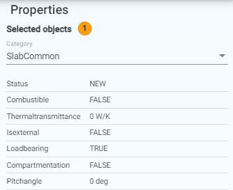
When an object is selected you can inspect properties through categories. You can also use attribute selection by clicking on a specific attribute in the Properties panel. All objects with the selected attribute and value will be selected in the 3D scene. This is very useful for cleaning the structure in the Convert Structural model to Analysis model workflow (step 2). When multiple objects are selected, you can toggle Show common properties at the top of the panel to see only the attributes and values they have in common. The result is shown in a category called "Shared properties". When the Show common properties toggle is turned OFF, properties for the last selected object are shown in the panel.

