Annexes
The annexes provide you with more information about specific parts of the ALLPLAN AutoConverter application. This information is outside of the user guide scope, but still very important and will help you to understand the processing behind the ALLPLAN AutoConverter functions.
Parallel Member Detection
Parallel member detection general condition:
-
Distance between center lines of elements is smaller than 25 centimeters.
-
Overlap in the length of elements merged together in at least 80%.
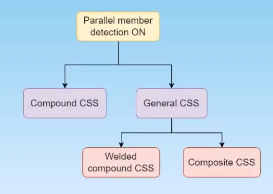
Figure 47: Parallel member detection diagram of processing -
Compound cross-section: When possible, compound cross-section (CSS) is created with priority. Members have to fulfill the general condition mentioned above, steel profiles have to be mapped to library profiles and compound type has to be supported. Supported compound types are mentioned below.
-
General cross-section: When profiles are not mapped or compound types are not supported, a general compound cross-section is created.
-
Welded compound cross-section: General compound cross-section consisting of multiple mapped steel profiles.
-
Composite compound cross-section: General compound consisting of more shapes or profiles and more than one material
Supported compound cross-section types:
-
Double I
-
Double channel
-
Starred angle
-
Double angle
-
Double pipe
All available compound cross-sections in SAF: SAF compound sections
System Line Positions
List of system line positions 1D:
-
Center
-
Top
-
Bottom
-
Left
-
Right
-
Top left
-
Top right
-
Bottom left
-
Bottom right
List of system lines positions 2D:
-
Top
-
Center
-
Bottom
List of eccentricities for 1D :
-
None
-
Y
-
Z
-
YZ
List of eccentricities for 2D:
-
None
-
Z

